Texturen,
Masken


Splines,
Geometrie


Polygonmodellen
Texturen
Transformationen
Framebuffer
OpenGL wurd von Silicon Graphics, Inc. entwickelt und ist auf unterschiedlichen Plattformen verfügbar. OpenGL entspricht einem Software-Interface, das weitgehend in C geschrieben ist und zum ( derzeitigen ) Industrie-Standard wurde. Diese Sammlung von Funktionen dient der Erstellung von hochwertigen graphischen Bildern. OpenGL nutzt ( auf unterster Ebene ) Frame-Buffer zur Behandlung von Antialiasing und Texturen und dient als Grundlage für zahlreiche Objekt-Bibliotheken.
OpenGL ist ein Software-System, das die folgenden Aufbereitungen von grafischen Daten unterstützt:
Drawing geometric shapes           Pixels, bitmaps, fonts, and images
Viewing and matrix transformations Texture mapping
Display lists                      Advanced composite techniques
Color                              Evaluators and NURBS
Lighting                           Selection and feedback
Blending, antialiasing, and fog    Advanced techniques
OpenGL ist eine Core-Bibliothek von Funktionen ( Software-Interface, #include <GL\gl.h>, OPENGL32.lib ). OpenGL unterstützt die Aufbereitung von Daten zur grafischen Repräsentation ( 2D, 3D ). OpenGL ist prozedural orientiert und netzwerktransparent. Es gibt ca. 300 Basis-Funktionen ( gl-Prefix ) um Objekte zu beschreiben, Matrizen - Transformationen durchzuführen, Farben zu behandeln, Texturen zu verwenden ( z.B. für Bitmaps, Fog und Antialiasing ). Ein typisches OpenGL-Programm richtet zunächst einen Frame-Buffer und GL-Kontext ein, die für die grafische Ausgabe der OpenGL-Befehle genutzt werden.
Vertex Daten beschreiben die Geometrie der Szene ( Punkte, Normalenvektoren, Linien, Polygone, Spline-Kurven und Flächen ). Pixel Daten sind Texturen für die Oberflächen und Schablonenmasken. Display Listen sind spezielle für die schnellere interne Verarbeitung aufbereitete Daten-Listen ( mit Geometrie- und Texturdaten ). Die Umwandlung der höheren Strukturen in Pixeldaten ( Rendering ) erfolgt nach dem folgenden Muster.
| Pixel Daten, Texturen, Masken | Display Listen | Vertex Daten, Splines, Geometrie | ||
| Pixel Operationen | Auswertung zu Polygonmodellen | |||
| Aufbereitung der Texturen | per Vertex Operationen Transformationen | |||
| Umwandlung in Rasterdaten | ||||
| Operationen auf Rasterdaten | ||||
Framebuffer |
Die OpenGL Programming Guide Auxiliary library ( #include <GL/glaux.h>, glaux.lib ) ist eine einfache Anpassung von OpenGL an die Fenstertechnik. Damit können Eingabe-Ereignisse und einfache Hintergrund-Prozesse behandelt werden. Diese aux-Bibliothek ist für Windows verfügbar. Die aux-Window-Klasse "tkLibWClass" enthält die CALLBACK-funktion tkWndProc(HWND hWnd, UINT message, DWORD wParam, LONG lParam) und die Nachrichten-Schleife für WM_-Nachrichten. tkWndProc() empfängt z.B. WM_SIZE-Nachrichten ( Fenstergröße ändern ) und bearbeitet diese gemäss:
 case WM_SIZE:
      windInfo.width  = LOWORD(lParam);
      windInfo.height = HIWORD(lParam);

      if ( ReshapeFunc ) {
         (*ReshapeFunc ) (windInfo.width, windInfo.height);
           ForceRedraw( hWnd );
      }  return (0);
Der aux-User hinterlegt in main() mit auxReshapeFunc( ReshapeFunc ) seine ReshapeFunc()-Funktion, die dann bei jeder WM_SIZE-Nachricht aufgerufen wird. Die Windows-Open GL-Bibliothek ( abgekürzt WGL ) behandeln den rendering contexts, display lists, extension functions, und die font bitmaps. Die WGL-Funktionen sind Erweiterungen für Windows und GLXdas X Window System. Die folgende Tabelle enthält die Gegenüberstellungen.
Die OpenGL Utility Library ( #include <GL/glu.h>, glu32.lib ) enthält weitere Funktionen für Texture, Koordinaten-Transformationen, Polygon Tessellation, Rendering Spheres, Zylinder und Scheiben. Mit OpenGLU können Non-Uniform Rational B-Spline Kurven und Flächen ( NURBS ) behandelt werden. Die Fehlerbehandlung wurde verbessert.
| Ohne "Fremd-Bibliotheken" können benutzt werden: | |||
| von Windows-Application : | GDI | WGL | OpenGL ( GL und GLU ) |
| von Unix-Application : | Xlib | GLX | OpenGL ( GL und GLU ) |
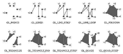
Viele OpenGL-Funktionen benutzen zum Zeichnen von grafischen Objekte "primitive" Elemente, wie
Andere Funktionen kontrollieren das Erscheinungsbild ( antialiasing, texturing ). Es werden die folgenden, OpenGL unterscheidet die draws primitives: point, line, segment, polygon, pixel rectangle. Ein Vertex definiert
OpenGL benutzt Funktionen mit C-Syntax. An einen Funktionsnamen werden ( bis zu 4 ) Buchstaben angehängt, die die Parametertypen beschreiben.
void Vertex3f ( float x, float y, float z ) ; void Vertex2fv ( float arr [2 ] ) ; // Allgemeine Form: rtype Name{1234} {b s i f d ub us ui} {v} ([args ,] T arg1 , _ _ _ , T argN [, args]); |
|
Zum Zeichnen wird oft der glVertex() - Aufruf verwendet, der zwischen der glBegin() und glEnd() stehen muss. Auch die Aufrufe von glVertex(), glColor(), glIndex(), glNormal(), glTexCoord() stehen zwischen der "glBegin-glEnd-Klammerung".
| GL_-Konstanten für mode: | |
 |
float x=-1, y=-1; enum mode=GL_LINE_STRIP; glBegin ( mode ) ; void glVertex2f(float x,float y); ... ... glEnd( ); |
  // Der Aufruf:
  float x1=-1,y1=-1, x2=1,y2=2;
  Rectf( x1, y1, x2, y2 );

  // entspricht
  glBegin ( GL_POLYGON ) ;
    glVertex2f( x1, y1 );
    glVertex2f( x2, y1 );
    glVertex2f( x2, y2 );
    glVertex2f( x1, y2 );
  glEnd ( ) ;
OpenGL-Fehler können mit
enum GetError ( void ) ;abgefragt werden.
Die Funktion glViewport( GLint iMin, GLint jMin, GLsizei w, GLsizei h ) erstellt die Matrix für die Umrechnung von normalisierte ( Welt-) Koordinaten -1.0 <= xnd <= +1.0, -1.0 <= ynd <= +1.0, auf Viewport-Koordinaten i, j. Der Mittelpunkt (0.0, 0.0) wird auf Viewport-Bezugspunkt(i0, j0) mit i0=(iMin+iMax)/2, i0=(jMin+jMax)/2 abgebildet.
Mit
    int i, iMin, iMax; float x, xMin, xMax;
    int j, jMin, jMax; float y, yMin, yMax;
ergibt sich aus

                     iMax - iMin
    i  =  iMin  +   ------------- ( x - xMin ),
                     xMax - xMin

                     jMax - jMin
    j  =  jMin  +   ------------- ( y - yMin ),
                     yMax - yMin

Die Spezialisierung auf normalisierte Koordinaten
x = xnd, y = ynd liefert mit

    xMin = yMin = -1.0,  w = iMax - iMin,
    xMax = yMax = +1.0,  h = jMax - jMin:

                      w
    i  =  iMin   +   --- ( xnd + 1.0 ),
                     2.0
                      h
    j  =  jMin   +   --- ( ynd + 1.0 ),
                     2.0
Für die Funktion void Viewport( int iMin, int jMin, sizei w, sizei h )
ergibt sich die 4x4-Matrix:
    (i)   ( w/2    0     0    iMin+w/2 )(xnd)
    (j) = (  0    h/2    0    jMin+h/2 )(ynd)
    (k)   (  0     0  [f-n]/2  (f+n)/2 )(znd)
    (1)   (  0     0     0       1     )( 1 )
Der k-Wert wird für den Tiefenbuffer verwendet ( DepthRange(n,f); 0 <= n,f <= 1 ).
| void glViewport( GLint iMin, GLint jMin, GLsizei w, GLsizei h ) |
Mit der Funktion void glGetIntegerv( GLenum pname, GLint * params ); können die mit Viewport() gesetzten Werte abgefragt werden:
int arr_ijwh[ 4 ];
glGetIntegerv( GL_VIEWPORT, arr_ijwh );
// liefert:
// int width = arr_ijwh[2];
// int high  = arr_ijwh[3];
Ist x eine x-Welt-Koordinate, so gilt mit Dx = (xMax-xMin)/2, Sx = (xMax+xMin)/2 für die normalisierte Koordinate xnd:
xMin <=  x   <= xMax
-1.0 <= xnd  <= 1.0


            xMax - xMin     xMax + xMin
x  = xnd . ------------  +  -----------
                 2               2

x  =   xnd  .   Dx       +      Sx


oder
         x      Sx
xnd  =  --- -  ----
        Dx      Dx
oder Umrechnung mit
   Si=(iMax+iMin)/2, Di=(iMax-iMin)/2,
   Sj=(jMax+jMin)/2, Dj=(jMax-jMin)/2,
   Sx=(xMax+xMin)/2, Dx=(xMax-xMin)/2,
   Sy=(yMax+yMin)/2, Dy=(yMax-yMin)/2,
ohne xnd :
   if (Di < Dj) Dy *= Dj/Di; else Dx *= Di/Dj;}
Umrechnung:
   i = x·(+Di/Dx) + (Si-Sx·Di/Dx)
   j = y·(-Dj/Dy) + (Sj+Sy·Dj/Dy)
Entsprechendes gilt für y und z. Durch glOrtho(xMin,xMax,yMin,yMax,zMin,zMax) oder gluOrtho2D( xMin,xMax, yMin,yMax) werden die Umrechnungskoeffizienten hinterlegt und gespeichert.
Der k-Wert wird für den Tiefenbuffer verwendet.
|
| void glViewport( GLint iMin, GLint jMin, GLsizei w, GLsizei h ) |
Mit der Funktion void glGetIntegerv( GLenum pname, GLint * params ); können die mit Viewport() gesetzten Werte abgefragt werden:
 int arr_ijwh[ 4 ];

 glGetIntegerv( GL_VIEWPORT, arr_ijwh );
ChangeSize() ist eine typische CALLBACK-Funktion, die beim Vergrößern des Fensters ( z.B. aufziehen mit der Maus ) vom System aufgerufen wird. Die user-definierten ChangeSize()-Funktion erhält als Parameter die aktuelle Fenstergrösse Fenstergröße ( w, h ), die dann mit glOrtho() oder gluOrtho2D() an das OpenGL-System übergeben wird. Bleibt der gewählte x,y-Welt-Ausschnitt fest, so würde eine anisotrope Abbildung entstehen (ein Kreis würde zur Ellipse ). Deshalb wird in glOrtho() oder gluOrtho2D() den Welt-Bereich vergrößert, damit auch beiFenster-Vergrösserung mit der Maus eine isotrope ( winkeltreue ) Abbildung ermöglicht wird:
void ChangeSize(int w, int h)
{
  if( w <= 0 ) w = 1;
  if( h <= 0 ) h = 1;  glViewport( 0,0, w, h );

  glMatrixMode( GL_MODELVIEW ); glLoadIdentity();
  if (w <= h) {
    glOrtho(xMin,xMax,yMin*h/w,yMax*h/w, -1.0,+1.0 );
  } else {
    glOrtho(xMin*w/h,xMax*w/h,yMin,yMax, -1.0,+1.0 );
  }
}
Der Aufruf glOrtho( xMin,xMax, yMin,yMax, -1.0, +1.0 ) entspricht gluOrtho2D( xMin,xMax, yMin,yMax ).
Mit double mat[4][4]; glGetDoublev( GL_MODELVIEW_MATRIX, &mat[0][0] ); kann die aktuelle GL_MODELVIEW_MATRIX-Matrix abgefragt werden.
Sind die Matrizen modelMatrix[16], projMatrix[16] und die viewport[4]-Werte bekannt, so rechnet die Funktion gluProject() einen Objekt-Punkt ( x,y,z ) in die Gerätekoordinaten ( i,j,k ) um.
int gluProject(
  GLdouble x, GLdouble y, GLdouble z,
  const GLdouble modelMatrix[16],
  const GLdouble projMatrix[16],
  const GLint viewport[4],
  GLdouble *i,
  GLdouble *j,
  GLdouble *k
);
Sind die Matrizen modelMatrix[16], projMatrix[16] und die viewport[4]-Werte bekannt, so rechnet die Funktion gluUnProject() die Gerätekoordinaten ( i,j,k ) in einen Objekt-Punkt ( x,y,z ) in um.
int gluUnProject(
  GLdouble i, GLdouble j, GLdouble k,
  const GLdouble modelMatrix[16],
  const GLdouble projMatrix[16],
  const GLint viewport[4],
  GLdouble *x,
  GLdouble *y,
  GLdouble *z
);
Mit den OpenGL-Funktionen glEnable( GL_LINE_SMOOTH ); glLineWidth(GLfloat width) können Linien dicker gezeichnet werden, indem der voreingestellt Strichdicken-Wert 1.0 geändert wird. Durch GLfloat rg[2]; glGetFloatv (GL_LINE_WIDTH_RANGE, rg); kann der mögliche Bereich für den Strichdicken-Parameter width abgefragt werden ( 0.5 ... 10.0 ). Die Strichart gepunktet kann z.B. mit glLineStipple( 1, 0x5555 ) erreicht werden. Hierbei ist 0x5555 = 0101 0101 0101 0101 bin das zu wiederholende Muster. Durch glLineStipple( 3, 0x5555 ) wird die Wiederholung je Bit verdreifacht, d.h. es ergeben sich anstelle von Einzelpunkten eine ( gröbere ) gestrichelte Linie.
void drawFigur( )
{
  glEnable( GL_LINE_STIPPLE );
  glLineStipple( 1, 0x22FF ); //0010 0010 1111 1111
  glEnable( GL_LINE_SMOOTH );
  glLineWidth( 1.8 );

  glBegin( GL_LINE_STRIP );
    glVertex2d( x1, y1 );
    glVertex2d( x2, y2 );
    ...
    ...
  glEnd();

  glDisable( GL_LINE_SMOOTH );
  glDisable( GL_LINE_STIPPLE );
}
Zum Zeichne von Linien, Linienstücken, Polygonen können bei OpenGL die PunktKoordinaten ( geklammert ) durch glBegin()... glVertex2d(PunktKoordinaten) ... glEnd() angegeben werden.
| Dreieck 1 | Dreieck 2 |
glColor3d( 0.0, 0.0, 1.0 ); glBegin( GL_LINE_STRIP ); glVertex2d( 0.0, 1.0 ); glVertex2d( 1.0, 0.0 ); glVertex2d(-1.0, 0.0 ); glVertex2d( 0.0, 1.0 ); glEnd(); | glColor3d( 1.0, 0.0, 0.0 ); glBegin( GL_LINE_LOOP ); glVertex2d( 0.0, 1.0 ); glVertex2d( 1.0, 0.0 ); glVertex2d(-1.0, 0.0 ); // GL_LINE_LOOP automatisch // zurück zum Anfangspunkt glEnd(); |
| Es werden zwei geschlossene Dreiecks-Linien-Züge gezeichnet. Die Linienfareben sind Dreieck 1, Dreieck 2 ) Durch glBegin( GL_LINE_LOOP ) ... glEnd() wird eine "Schlusslinie" hinzugefügt. Durch glBegin( GL_POLYGON ) wird das Dreieck mit der aktuellen Farbe gefüllt. | |
Hier werden 3 Methoden ( Bitmaps, Liniensegmente, Texturen ) gezeigt, um Text anzuzeigen ( nur das Prinzip, nicht unmittelbar lauffähig ).
 // Liste fuer Bitmaps
 for i = start + 'a' to start + 'z'
 {

   glBeginList(i);
     glBitmap( ... );
   glEndList();

 }
 // Ausgabe
 glRasterPos3i(x, y, z);
 glListBase(start);
 glCallLists("Bitmapped Text", 14, GL_BYTE);
 //Liste für Linien-Segmente:
 glTranslate(ox, oy, 0);
   glBegin(GL_LINES);
     glVertex(...);
     ...
   glEnd();
 glTranslate(dx-ox, dy-oy, 0);
 // Liste für Texturen
 glTranslate(ox, oy, 0);
   glBegin(GL_QUADS)
     glTexCoord( ... );
     glVertex( ... );
     ...
   glEnd();
 glTranslate(dx-ox, dy-oy, 0);

 // Ausgabe
 glCallList(TEX);
 glCallLists("Texture mapped text!!", 22, GL_BYTE);
Mit id = glGenLists(1); kann eine freie id-Nummer erhalten werden. Durch glDeleteLists(id, 1) ist der alokierte Speicherbereich wieder freizu geben.
//--------------------------------
// Definieren einer Display-Liste:
//--------------------------------
#define  ID_MYLIST1  101

glNewList( ID_MYLIST1, GL_COMPILE);
  GLdouble x,y, u; int k, nn = 20;
  //glMatrixMode(GL_MODELVIEW);
  //glCullFace( GL_BACK ); //GL_FRONT

  glBegin( GL_POLYGON );
    for ( int k = 0; k < nn; k++ ) {
      u = PI*2*k/nn;
      x = cos( u );
      y = sin( v );
      glVertex2d( x, y );
    }
  glEnd();
glEndList();

//--------------------------------
// Aufruf einer Display-Liste:
//--------------------------------
glCallList( ID_MYLIST1 );
Ab OpenGL 1.1 können Vertex Arrays bereitgestellt werden,
die mit Hilfe nur eines Funktionsaufrufes angezeigt werden ( Vorteil: Geschwindigkeit ).
Diese ermöglichen die Übergabe mehrerer Vertex-Daten
mit Hilfe nur eines Funktionsaufrufes,
was natürlich entscheidende Geschwindig-keitsvorteile bringt.
Folgende Daten können in Vertex Arrays untergebracht werden:
Der Befehl glEnableClientState( GLenum arraytyp) aktiviert die Nutzung eines der oben genannten Arrays. Es macht keinen Sinn z.B. das COLOR_ARRAY UND das INDEX_ARRAY einzuschalten, weil nur eines gültig genutzt werden kann. Der Befehl glVertexPointer( GLint size, GLenum type, GLsizei stride, const GLvoid *pArr) spezifiziert das Array mit den Koordinateninformationen. Der OpenGL wird mitgeteilt, wo die Koordinatendaten zu finden sind ( *pArr), wieviele Koordinaten pro Punkt es gibt ( size), welchen Typ sie haben ( type) und wieviel Bytes Abstand zwischen der jeweils ersten Koordinate der Punkte sind ( stride). Ist stride gleich Null, so werden die Koordinaten als direkt hintereinanderstehend interpretiert. Dies ist dann der Fall, wenn sich nur Koordinateninformationen in dem Array befinden. Die Spezifizierung der anderen Arrays erfolgt analog mit den Befehlen
 void glVertexPointer(
   GLint    size,
   GLenum   type,
   GLsizei  stride,
   const GLvoid* pointer
 );

size   : number of coordinates per vertex
         (2,3 or 4)
type   : data type of each coordinate
         in the array GL_SHORT, GL_INT,
         GL_FLOAT, and GL_DOUBLE.
stride : byte offset between
         consecutive vertices
pointer: to the first coordinate
         of the first array-vertex
In dem folgenden Beispiel werden Arrays definiert ( Farben der Punkte, Punktkoordinaten ). glEnableClientState( GL_COLOR_ARRAY) schaltet die Nutzung des Farb-Arrays ein.
void display(void) {
  static GLfloat colors[]    = { 1.0, 0.0, 0.0,
                                 0.0, 1.0, 0.0,
                                 0.0, 0.0, 1.0 };
  static GLfloat vertices[] = { -0.75, -0.75,
                                 0.75, -0.75,
                                 0.00,  0.75 };
  glEnableClientState( GL_COLOR_ARRAY );
  glEnableClientState( GL_VERTEX_ARRAY );
  // Einstellen der Infos ueber die Arrays
  // Daten pro Vertex, Element-Typ, Abstand, Zeiger auf Feld
  glColorPointer(  3, GL_FLOAT, 0, colors );
  glVertexPointer( 2, GL_FLOAT, 0, vertices );
  glClear( GL_COLOR_BUFFER_BIT);

  glBegin( GL_POLYGON);
    // Nutzung von Arrays|------ohne Array-Funktionen ------------
    glArrayElement(0);//glColor3f(1,0,0);glVertex2f(-0.75,-0.75);
    glArrayElement(1);//glColor3f(0,1,0);glVertex2f( 0.75,-0.75);
    glArrayElement(2);//glColor3f(0,0,1);glVertex2f( 0.00, 0.75);
  glEnd();

  glFlush();
 }

 void init( void) {
   glClearColor( 0.0, 0.0, 0.0, 1.0);
   glOrtho(-1.0,1.0, -1.0,1.0, -1.0,1.0);
 }
 int main( int argc, char** argv){
   glutInit( &argc, argv);
   glutInitDisplayMode( GLUT_RGB);
   glutCreateWindow( argv[0]);
   glutDisplayFunc( display);
   init(); glutMainLoop(); return 0;
 }
Wurde ein Vertex Array definiert, so kann dieser mehrfach genutzt werden. Das folgende Beispiel ist für einen Würfel gedacht. Jeder Eckpunkt grenzt an 3 Flächen. Jede Fläche hat 4 Eckpunkte. Es gibt 8 Eckpunkte und 6 begrenzende ( ebene ) Flächen. Mit dem Befehl glDrawElements( GLenum mode, GLsizei count, GLenum type, void *indices); werden die die Punkte eines Vertex Arrays mehrfach genutzt.
void display( void){ // Würfel
// Koordinaten-Array der einzelnen Punkte
   static GLfloat P[]= {
    -0.5, -0.5,  0.5,  // Punkt 0
     0.5, -0.5,  0.5,  // Punkt 1
     0.5,  0.5,  0.5,  // Punkt 2
    -0.5,  0.5,  0.5,  // Punkt 3
    -0.5, -0.5, -0.5,  // Punkt 4
     0.5, -0.5, -0.5,  // Punkt 5
     0.5,  0.5, -0.5,  // Punkt 6
    -0.5,  0.5, -0.5 };// Punkt 7

// Array indiziert die Punkte aus P[]
  static GLubyte K[]=
   { 0, 1, 2, 3,   // front
     3, 2, 6, 7,   // top
     0, 3, 7, 4,   // left
     2, 1, 5, 6,   // right
     1, 0, 4, 5,   // bottom
     5, 4, 7, 6 }; // back

 int j; // Anzahl von Kanten je Fläche

 glEnableClientState( GL_VERTEX_ARRAY);
   glVertexPointer( 3, GL_FLOAT, 0, P);
  glClear( GL_COLOR_BUFFER_BIT);
  glRotated( 20, 1.0, 1.0, 1.0);
  for( j=0; j < 6; j++)
  // zeichnet ein LINE_LOOP aus den
  // in K[] referenzierten Punkten
  glDrawElements(GL_LINE_LOOP,4,GL_UNSIGNED_BYTE,&K[4*j]);
  glFlush();
}

void init( void){
  glClearColor( 0.0, 0.0, 0.0, 1.0);
  glOrtho(-1.0,1.0, -1.0,1.0, -1.0,1.0);
}
int main( int argc, char **argv){
  glutInit( &argc, argv);
  glutInitDisplayMode( GLUT_RGB);
  glutCreateWindow( argv[0]);
  glutDisplayFunc( display);
  init(); glutMainLoop(); return 0;
}
void glDrawArrays(
  GLenum  mode,  // z.B.   GL_POLYGON
  GLint   first, // erster Punkte-Index
  GLsizei count  // Anzahl von Punkten
);

mode :
  GL_POINTS, GL_LINE_STRIP, GL_LINE_LOOP,
  GL_LINES, GL_POLYGON, GL_TRIANGLE_STRIP,
  GL_TRIANGLE_FAN, GL_TRIANGLES,
  GL_QUAD_STRIP, GL_QUADS
first : starting index in the enabled arrays.
count : number of indexes to render
Eine Methode benutzt einen Array ( pArr ), in dem die 2D-Punkte hinterlegt werden. Zum Zeichnen eines Array-Bereiches wird glDrawArrays() verwendet.
GLdouble pArr[][2] = { x_min, 0.0,
                       x_max, 0.0,
                       0.0,   y_max,
                       0.0,   y_min };

int n_max = sizeof(pArr)/sizeof(pArr[0]);

glEnableClientState( GL_VERTEX_ARRAY );
  glVertexPointer( 2, GL_DOUBLE,0, pArr);
  glDrawArraysDrawArrays( GL_POLYGON, 0, n_max);
glDisableClientState( GL_VERTEX_ARRAY );


glEnableClientState( GL_VERTEX_ARRAY );
  glVertexPointer( 2, GL_DOUBLE,0, pArr);
  glBegin(GL_POLYGON);
    glColor3d(1.0,0.0,0.0); glArrayElement(0);
    glColor3d(0.0,1.0,0.0); glArrayElement(1);
    glColor3d(0.0,0.0,1.0); glArrayElement(2);
  glEnd();
glDisableClientState( GL_VERTEX_ARRAY );
Mit OpenGL kann die Strichart einer Linie mit dem LineStipple (
Stripple-"Füllung" ) beeinflußt werden. Die Strichart
gepunktet kann z.B. mit glLineStipple( 1, 0x5555 ) erreicht
werden. Hierbei ist das glLineStipple-
Bitmuster: 0x5555 = 0101 0101 0101 0101 bin
das zu wiederholende Muster. Durch glLineStipple( 3, 0x5555 ) wird die
Wiederholung je Bit verdreifacht, d.h. es ergeben sich anstelle von
Einzelpunkten eine ( gröbere ) gestrichelte Linie.
void drawFigur( )
{
  glEnable( GL_LINE_STIPPLE );
  glLineStipple( 1, 0x22FF ); //0010 0010 1111 1111
  glEnable( GL_LINE_SMOOTH );
  glLineWidth( 1.8 );
  glBegin( GL_LINE_STRIP );
    glVertex2d( x1, y1 );
    glVertex2d( x2, y2 );
    ...
    ...
  glEnd();
  glDisable( GL_LINE_SMOOTH );
  glDisable( GL_LINE_STIPPLE );
}
Ein ebenes Polygon ist eine ebene, geradlinie begrenzte, geschlossene Fläche. Für ein Polygon werden die Eckpunkte vorgegeben. Der Polygon-Rand ist durch die Reihenfolge der Eckpunkte festgelegt. Beim Füllen des Polygons kann ein Bit-Füllmuster ( PolygonStipple ) verwednet werden. Ein solches Bitmuster besteht aus 32x32 Bit. Beim Füllen wird das Bitmuster ggf. wiederholt.
Im folgenden Beispiel wird das Bitmuster stripple_4 verwendet.
| PolygonStipple-Bitmuster |
GLubyte stripple_4[] = {
0xFF, 0x00, 0xFF, 0x00,/* 11111111 ........ 11111111 ........*/
0xFF, 0x00, 0xFF, 0x00,/* 11111111 ........ 11111111 ........*/
0xFF, 0x00, 0xFF, 0x00,/* 11111111 ........ 11111111 ........*/
0xFF, 0x00, 0xFF, 0x00,/* 11111111 ........ 11111111 ........*/
0xFF, 0x00, 0xFF, 0x00,/* 11111111 ........ 11111111 ........*/
0xFF, 0x00, 0xFF, 0x00,/* 11111111 ........ 11111111 ........*/
0xFF, 0x00, 0xFF, 0x00,/* 11111111 ........ 11111111 ........*/
0xFF, 0x00, 0xFF, 0x00,/* 11111111 ........ 11111111 ........*/
0x00, 0xFF, 0x00, 0xFF,/* ........ 11111111 ........ 11111111*/
0x00, 0xFF, 0x00, 0xFF,/* ........ 11111111 ........ 11111111*/
0x00, 0xFF, 0x00, 0xFF,/* ........ 11111111 ........ 11111111*/
0x00, 0xFF, 0x00, 0xFF,/* ........ 11111111 ........ 11111111*/
0x00, 0xFF, 0x00, 0xFF,/* ........ 11111111 ........ 11111111*/
0x00, 0xFF, 0x00, 0xFF,/* ........ 11111111 ........ 11111111*/
0x00, 0xFF, 0x00, 0xFF,/* ........ 11111111 ........ 11111111*/
0x00, 0xFF, 0x00, 0xFF,/* ........ 11111111 ........ 11111111*/
0xFF, 0x00, 0xFF, 0x00,/* 11111111 ........ 11111111 ........*/
0xFF, 0x00, 0xFF, 0x00,/* 11111111 ........ 11111111 ........*/
0xFF, 0x00, 0xFF, 0x00,/* 11111111 ........ 11111111 ........*/
0xFF, 0x00, 0xFF, 0x00,/* 11111111 ........ 11111111 ........*/
0xFF, 0x00, 0xFF, 0x00,/* 11111111 ........ 11111111 ........*/
0xFF, 0x00, 0xFF, 0x00,/* 11111111 ........ 11111111 ........*/
0xFF, 0x00, 0xFF, 0x00,/* 11111111 ........ 11111111 ........*/
0xFF, 0x00, 0xFF, 0x00,/* 11111111 ........ 11111111 ........*/
0x00, 0xFF, 0x00, 0xFF,/* ........ 11111111 ........ 11111111*/
0x00, 0xFF, 0x00, 0xFF,/* ........ 11111111 ........ 11111111*/
0x00, 0xFF, 0x00, 0xFF,/* ........ 11111111 ........ 11111111*/
0x00, 0xFF, 0x00, 0xFF,/* ........ 11111111 ........ 11111111*/
0x00, 0xFF, 0x00, 0xFF,/* ........ 11111111 ........ 11111111*/
0x00, 0xFF, 0x00, 0xFF,/* ........ 11111111 ........ 11111111*/
0x00, 0xFF, 0x00, 0xFF,/* ........ 11111111 ........ 11111111*/
0x00, 0xFF, 0x00, 0xFF,/* ........ 11111111 ........ 11111111*/
}; //GLubyte stripple_4[]
|
| Rechteck- Muster- Füllung | Polgon- Muster- Füllung |
glEnable ( GL_POLYGON_STIPPLE ); glPolygonStipple( stripple_4 ); glRectd ( x1,y1, x2,y2 ); glDisable (GL_POLYGON_STIPPLE); | glEnable ( GL_POLYGON_STIPPLE ); glPolygonStipple( stripple_4 ); glBegin( GL_POLYGON ); glVertex2d( x1, y1 ); glVertex2d( x2, y2 ); ... glEnd(); glDisable ( GL_POLYGON_STIPPLE ); |
Mit dem Aufruf von Funktionen ( wie z.B. glOrtho(), glTranslated(), glScaled(), glRotated(), usw. ) besetzt OpenGL intern eine neue 4x4-Matrix, die die aktuelle Matrik auf dem Matrizenstack multipliziert. Die Einheitsmatrix wird durch glLoadIdentity() auf dem Stack hinterlegt. Durch glOrtho() wird eine 4x4-Matrix besetzt, die das Rechteck (left, bottom, -near), (right, top, -near) auf das Bildschirm-Fenster abgebildet. Das Auge befindet sich bei (0, 0, 0).
OpenGL unterstütz Matrix-Operationen. Durch Funktionen werden intern 4x4-Matrizen besetzt und im MODELVIEW-Stack oder PROJECTION-Stack in der auftretenden Reihenfolge zu einer Ergebnismatrix multipliziert. Beispiele sind:
|
glMatrixMode( GL_MODELVIEW ) glLoadIdentity() glTranslated() glScaled() glRotated() |
glMatrixMode( GL_PROJECTION) glLoadIdentity() gluPerspective() |
glOrtho() gluOrtho2D() |
Für die grafische Darstellung werden alle Punkte einer Folge von Vertex-Transformationen unterworfen:
| Eye- Koordinaten | xe ye ze we | = | Modell- View- Matrix | x y z w | Objekt- Koordinaten |
| Clip- Koordinaten | xp yp zp wp | = | Projektions- Matrix | xe ye ze we | Eye- Koordinaten |
| Normalisierte- Device- Koordinaten | xd yd zd 1 | = | Division xp/wp yp/wp yp/wp | xp yp zp wp | Clip- Koordinaten |
| Window- Geräte- Koordinaten | i j k 1 | = | Viewport- Transformation | xd yd zd 1 | Normalisierte- Device- Koordinaten |
| Darstellung | i j k 1 | Window- Geräte- Koordinaten |
Um aus 3D-Daten ein Bild zu erstellen, sind zahlreiche Matrizenoperationen erforderlich. Vertices und Normalen werden im Modellraum und bei der Projektion transformiert.
| Matrizen Trans- formationen | glMatrixMode glMultMatrix* glRotate* glTranslate* glScale* | werden für die gewünschten Matrizen-Transformationen benutzt |
| Matrizen Stack | glglLoadMatrix* glLoadIdentity glPushMatrix glPopMatrix | werden für die Zwischenspeicherung der Matrizen auf dem Stack verwendet |
| Setzen der Beleuchtung | glLight* glLightModel* | setzt Farbe, Beleuchtung, Normalenvektor |
| Setzen der Material- eigenschaften, Berechnungen | glMaterial* glShadeModel glFrontFace glColorMaterial | setzt für das Beleuchtungsmodell die benötigten Materialeigenschaften |
| Generiert Textur- Kooerdinaten | glTexGen* | nachdem die Textur-Kooerdinaten mit glTexGen* erstellt sind, werden diese mit der vorhandenen Matrix transformiert. |
Anstelle der OpenGL-Funktionen glTranslated(), glOrtho() können die folgenden Funktionen gl_Translated(), gl_Ortho() verwendet werden:
void gl_LoadIdentity() {
  double m[4][4];
  m[0][0]=+1.0; m[1][0]= 0.0; m[2][0]= 0.0; m[3][0]= 0.0;
  m[0][1]= 0.0; m[1][1]=+1.0; m[2][1]= 0.0; m[3][1]= 0.0;
  m[0][2]= 0.0; m[1][2]= 0.0; m[2][2]=+1.0; m[3][2]= 0.0;
  m[0][3]= 0.0; m[1][3]= 0.0; m[2][3]= 0.0; m[3][3]=+1.0;
  glLoadMatrixd( & m[0][0] );
}
Die Funktion glLoadMatrixd(const GLdouble *MAT ) überschreibt die aktuelle 4x4-Stack-Matrix mit der 4x4-Matrix MAT.
      ( a[0] | a[4] | a[8] | a[12] )
      ( a[1] | a[5] | a[9] | a[13] )
MAT = ( a[2] | a[6] | a[10]| a[14] )
      ( a[3] | a[7] | a[11]| a[15] )
void gl_Scaled(double sx,double sy,double sz)
{
  double m[4][4];
  m[0][0]=  sx; m[1][0]= 0.0; m[2][0]= 0.0; m[3][0]= 0.0;
  m[0][1]= 0.0; m[1][1]=  sy; m[2][1]= 0.0; m[3][1]= 0.0;
  m[0][2]= 0.0; m[1][2]= 0.0; m[2][2]=  sz; m[3][2]= 0.0;
  m[0][3]= 0.0; m[1][3]= 0.0; m[2][3]= 0.0; m[3][3]=+1.0;
  glMultMatrixd( & m[0][0] );
}
void gl_Translated(double tx,double ty,double tz) {
  double m[4][4];
  m[0][0]=+1.0; m[1][0]= 0.0; m[2][0]= 0.0; m[3][0]= tx;
  m[0][1]= 0.0; m[1][1]=+1.0; m[2][1]= 0.0; m[3][1]= ty;
  m[0][2]= 0.0; m[1][2]= 0.0; m[2][2]=+1.0; m[3][2]= tz;
  m[0][3]= 0.0; m[1][3]= 0.0; m[2][3]= 0.0; m[3][3]=+1.0;
  glMultMatrixd( & m[0][0] );
}
void gl_Rotated(double a, double u,double v,double w) {
  double m[16]; a *= -PI/180.0;
  double len = sqrt(u*u+v*v+w*w) ;
  if ( len < 1E-38 ) return;
  u /=len; v /=len; w /=len; // Einheitsvektor
  double ss = sin(a);
  double cc = cos(a); double t = (1.0-cc);
  double tuv=t*u*v; double tuu=t*u*u; double uu=ss*u ;
  double tuw=t*u*w; double tvv=t*v*v; double vv=ss*v ;
  double tvw=t*v*w; double tww=t*w*w; double ww=ss*w ;

  m[0]=tuu+cc; m[4]=tuv+ww; m[ 8]=tuw-vv; m[12]=0.0;
  m[1]=tuv-ww; m[5]=tvv+cc; m[ 9]=tvw+uu; m[13]=0.0;
  m[2]=tuw+vv; m[6]=tvw-uu; m[10]=tww+cc; m[14]=0.0;
  m[3]=   0.0; m[7]=  0.0 ; m[11]=   0.0; m[15]=1.0;
  glMultMatrixd( & m[0] );
}
Die Funktion glMultMatrixd(const GLdouble *MAT ) multipliziert die aktuelle 4x4-Stack-Matrix mit der 4x4-Matrix MAT.
      ( a[0] | a[4] | a[8] | a[12] )
      ( a[1] | a[5] | a[9] | a[13] )
MAT = ( a[2] | a[6] | a[10]| a[14] )
      ( a[3] | a[7] | a[11]| a[15] )
void gl_Ortho(double x1, double x2,
              double y1, double y2,
              double z1, double z2)
{
  double m[16],dx=(x2-x1),dy=(y2-y1),dz=(z2-z1);
  m[0]=2./dx;m[4]= 0.0; m[ 8]= 0.0; m[12]=(x1 + x2)/dx;
  m[1]= 0.0; m[5]=2./dy;m[ 9]= 0.0; m[13]=(y1 + y2)/dy;
  m[2]= 0.0; m[6]= 0.0; m[10]=2./dz;m[14]=(z1 + z2)/dz;
  m[3]= 0.0; m[7]= 0.0; m[11]= 0.0; m[15]=+1.0 ;
  glMultMatrixd( & m[0] );
}
Es gibt zahlreiche glu-Funktionen:
| gluBeginCurve, gluEndCurve | The gluBeginCurve and gluEndCurve functions delimit a Non-Uniform Rational B-Spline (NURBS) curve definition. |
| gluBeginPolygon, gluEndPolygon | The gluBeginPolygon and gluEndPolygon functions delimit a polygon description. |
| gluBeginSurface, gluEndSurface | The gluBeginSurface and gluEndSurface functions delimit a NURBS surface definition. |
| gluBeginTrim, gluEndTrim | The gluBeginTrim and gluEndTrim functions delimit a NURBS trimming loop definition. |
| gluBuild1DMipmaps | The gluBuild1DMipmaps function creates 1-D mipmaps. |
| gluBuild2DMipmaps | The gluBuild2DMipmaps function creates 2-D mipmaps. |
| gluCylinder | The gluCylinder function draws a cylinder. |
| gluDeleteNurbsRenderer | The gluDeleteNurbsRenderer function destroys a NURBS object. |
| gluDeleteQuadric | The gluDeleteQuadric function destroys a quadric object. |
| gluDeleteTess | The gluDeleteTess function destroys a tessellation object. |
| gluDisk | The gluDisk function draws a disk. |
| gluErrorString | The gluErrorString function produces an error string from an OpenGL or GLU error code. The error string is ANSI only. |
| gluGetNurbsProperty | The gluGetNurbsProperty function gets a NURBS property. |
| gluGetString | The gluGetString function gets a string that describes the GLU version number or supported GLU extension calls. |
| gluGetTessProperty | The gluGetTessProperty function gets a tessellation object property. |
| gluLoadSamplingMatrices | The gluLoadSamplingMatrices function loads NURBS sampling and culling matrices. |
| gluLookAt | The gluLookAt function defines a viewing transformation. |
| gluNewNurbsRenderer | The gluNewNurbsRenderer function creates a NURBS object. |
| gluNewQuadric | The gluNewQuadric function creates a quadric object. |
| gluNewTess | The gluNewTess function creates a tessellation object. |
| gluNextContour | The gluNextContour function marks the beginning of another contour. |
| gluNurbsCallback | The gluNurbsCallback function defines a callback for a NURBS object. |
| gluNurbsCurve | The gluNurbsCurve function defines the shape of a NURBS curve. |
| gluNurbsProperty | The gluNurbsProperty function sets a NURBS property. |
| gluNurbsSurface | The gluNurbsSurface function defines the shape of a NURBS surface. |
| gluOrtho2D | The gluOrtho2D function defines a 2-D orthographic projection matrix. |
| gluPartialDisk | The gluPartialDisk function draws an arc of a disk. |
| gluPerspective | The gluPerspective function sets up a perspective projection matrix. |
| gluPickMatrix | The gluPickMatrix function defines a picking region. |
| gluProject | The gluProject function maps object coordinates to window coordinates. |
| gluPwlCurve | The gluPwlCurve function describes a piecewise linear NURBS trimming curve. |
| gluQuadricCallback | The gluQuadricCallback function defines a callback for a quadric object. |
| gluQuadricDrawStyle | The gluQuadricDrawStyle function specifies the draw style desired for quadrics. |
| gluQuadricNormals | The gluQuadricNormals function specifies what kind of normals are to be used for quadrics. |
| gluQuadricOrientation | The gluQuadricOrientation function specifies inside or outside orientation for quadrics. |
| gluQuadricTexture | The gluQuadricTexture function specifies whether quadrics are to be textured. |
| gluScaleImage | The gluScaleImage function scales an image to an arbitrary size. |
| gluSphere | The gluSphere function draws a sphere. |
| gluTessBeginContour, gluTessEndContour | The gluTessBeginContour and gluTessEndContour functions delimit a contour description. |
| gluTessBeginPolygon, gluTessEndPolygon | The gluTessBeginPolygon and gluTessEndPolygon functions delimit a polygon description. |
| gluTessCallback | The gluTessCallback function defines a callback for a tessellation object. |
| gluTessNormal | The gluTessNormal function specifies a normal for a polygon. |
| gluTessProperty | The gluTessProperty function sets the property of a tessellation object. |
| gluTessVertex | The gluTessVertex function specifies a vertex on a polygon. |
| gluUnProject | The gluUnProject function maps window coordinates to object coordinates. |
Beispiel: Mit Hilfe von glu-Funktionen wird ein Kegelmantel als Gitternetz gezeichnet.
void draw_kegelmantel(void)
{
  static int nr;
  if(nr) { // oft aufrufen
    glCallList(nr);
  } else { // aber ... nur einmal anlegen!

    GLUquadricObj *pObj = gluNewQuadric();


            nr = glGenLists(1);
  glNewList(nr,GL_COMPILE_AND_EXECUTE);
    glPushMatrix ();


  glRotated(-90.0, 1.0, 0.0, 0.0);
  //glTranslated(   0.0, 0.0,-1.0);
  //GLU_LINE,GLU_SILHOUETTE,GLU_FILL
  gluQuadricDrawStyle(pObj,GLU_LINE);
  gluQuadricNormals(  pObj,GLU_SMOOTH);
  //         r0,r1,h, nSektoren,nScheiben,
  gluCylinder(pObj,1.0,0.0,1.0, 8,3);

    glPopMatrix ();
  glEndList();

    gluDeleteQuadric(pObj);
  }
}